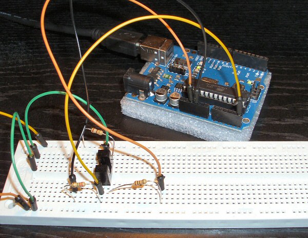
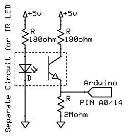
As I mentioned in the last post, I finally got my photo interrupter to react under the Arduino, using an Analog pin.
Now for my project this was fine, as I had actually allotted one analog pin for this detector, as the digital ones would all be in use. But analog is slow (about 110us), much slower than a digital detect, and I worried this slowness would someday come back and cause problems.

So I looked at the circuit I was using, and realized something: the analog output value of 200 was quite low. I was thinking of 255 as the upper limit for analog, but in fact it runs from 0-1023. This means that 200 was about 20% of a full signal, and possibly that was why I couldn’t get a digital reading.
So I set about increasing the ‘on’ signal.  The pulldown resistor (from ground to the pin, to make ‘0v’ nice and clean) was about 10k; perhaps it was interfering somehow. So I tried higher: 100k, 1meg, 2.2meg, and finally, 3.3meg. And as I increased it, the maximum reading rose on the pin, from around 200 to over 1000. In the end, I decided 1.5-2meg would do the job, making the ‘on’ reading near 1000, while keeping the ‘off’ near zero.
The next step, now that I had a nice wide range, was to try it on a digital test. For that, I switched to the DigitalReadSerial sketch, but with a twist: I was going to continue calling the analog pin, but as a digital pin (this way, I knew nothing would change, since I moved no wires). The Arduino analog pins A0-A5 can be referred to as digital pins 14-19 (A0 is 14, A1 is 15, etc). So, my test wire in pin A5 was 19, and I just changed that in the digital sketch and ran it.
And just like that, I got my slotted optical detector’s on/off signal to come in clean as a 0/1 digital signal!
So, the moral of the story? No moral, but here’s some useful steps:
- Try to test everything first completely away from the Arduino – it saves some complications you don’t need at the start.
- Reference guides are invaluable, especially if the online information is meager.
- Test slowly and carefully, and use resistors everywhere to limit current – you can always remove them, but adding them after you’ve blown a component won’t help.
- Check amperage. The Arduino is limited to 40mA per pin, so always do the math and make sure you’re not hooking up a potential overload circuit. Remember, R = V / I, so at 5v, you need at least 125 ohms of resistance to prevent going over 40mA (and it pays to be much higher than that, since all the pins together have a total current requirement).
- Consider using an Analog pin to check levels. In my case, I could check the voltage with AnalogReadSerial and tweak until I got a digital signal that did the trick. Otherwise, I’d have been in the dark as to what was happening – or how to fix it.
That’s it for now – I have my photo interruptor ready to go, and so it’s time to learn something else new on the Arduino…
(Not quite – check out optos part 3 for the final finished result…)

The issue is that your pull-up on the IR phototransistor is far too “strong”, making it nearly impossible for the light-current to drive it low. A typical pull-up on a phototransistor in this arrangement would be around 10k ohms, not 180!
Also, you want to put your Arduino input on the “high” side of the phototransistor.
With a 10k you should get a nice clean signal very close to zero volts when the beam is not blocked, and still have Vcc when the beam is broken.
Photointerrupters/reflectors are wired intuitively “backwards”, where a valid “reflection” or beam drives a zero voltage on the associated input.
Found a simple example: http://www.sparkfun.com/datasheets/PCB/PI-1120%20Breakout.pdf
Thanks – using that schematic, I wrote another article with a simpler design for the sensor circuit: https://www.utopiamechanicus.com/article/opto-interrupter-part-3/